Challenge
Design and test a scale model of a bridge with maximum strength and minimal material, within several design constraints.
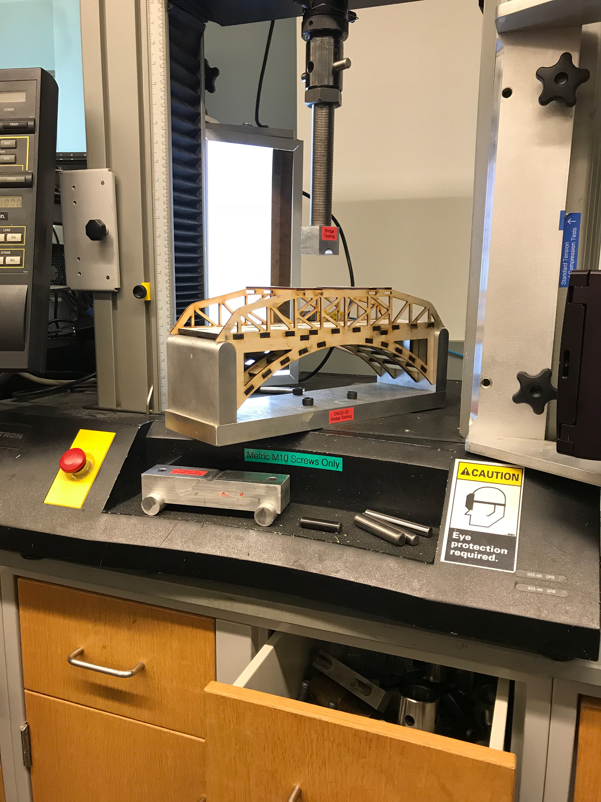
Instron Testing
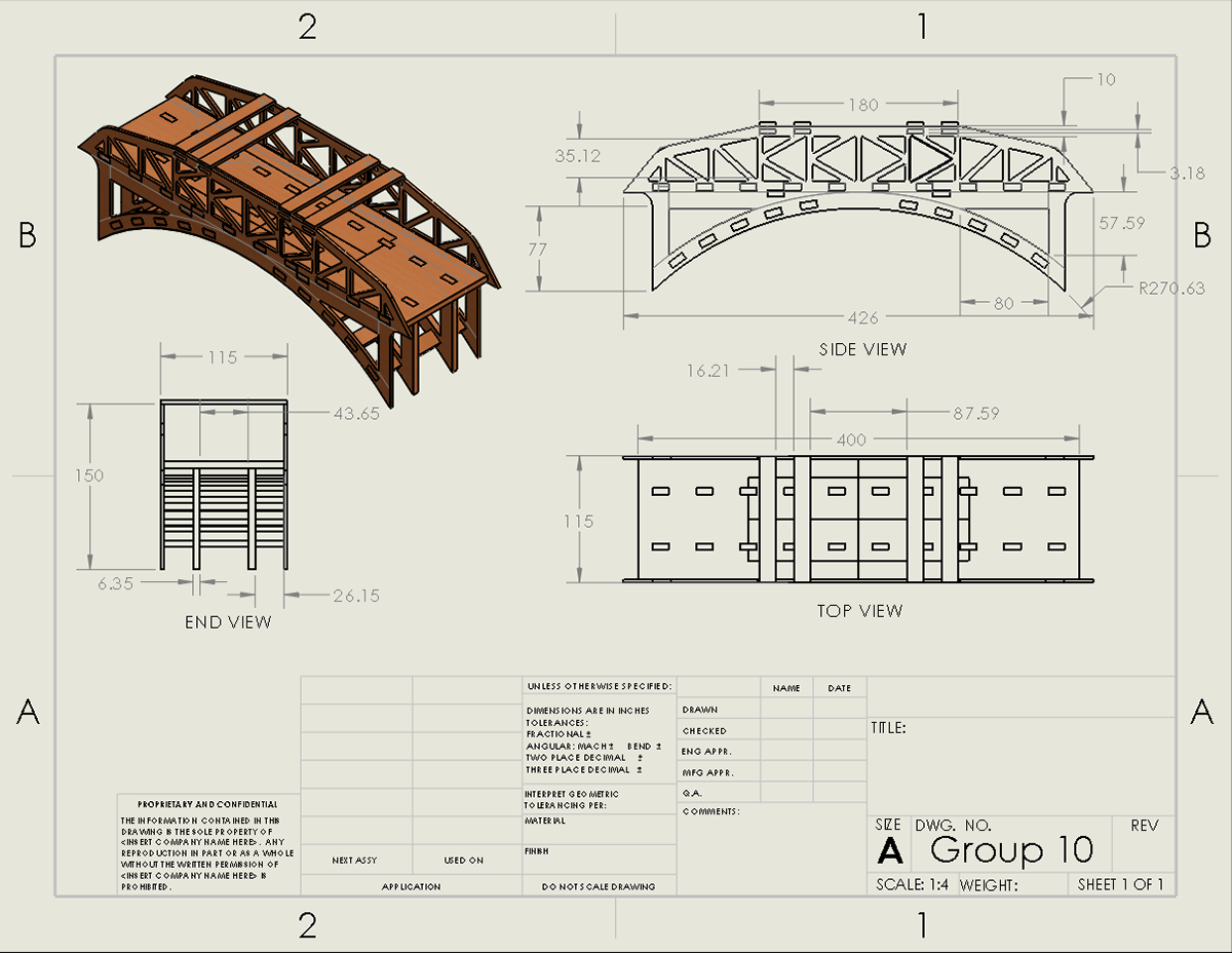
2D CAD
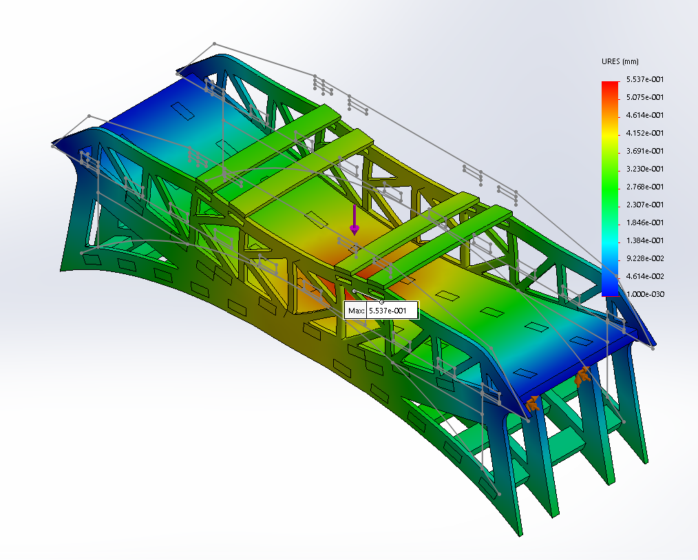
FEA: Max Displacement
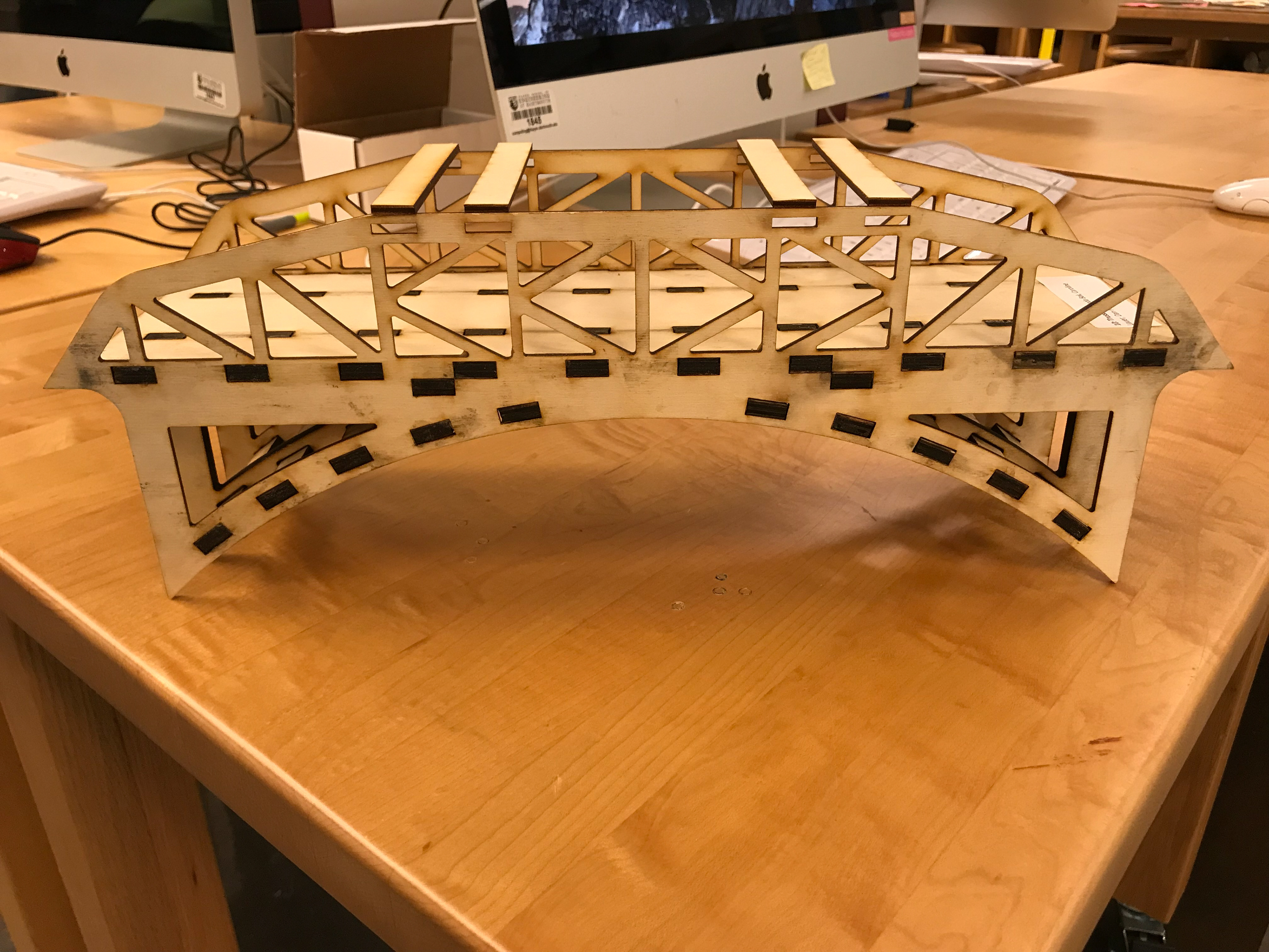
Front View
Project Overview
For my Solid Mechanics class, we were tasked with designing a bridge that was economical (low weight), strong (supports a high load), and stiff (small deflections), in addition to being creative and aesthetically pleasing. Our bridge was going to be tested by applying a load along its mid-span using an Instron Testing Machine, so we were also expected to predict, with close accuracy, its maximum load, maximum deflection at a load of 1 kN, and location of failure.
The primary design constraints were time and dimensions. We had 3 weeks to complete this project and could only laser cut plywood to fabricate our final bridge.
This project was actually one of my favorites because I really enjoyed the direct application of the solid mechanics theories we were learning to constructing, analyzing, and testing our bridge.
Design Process & Results
To begin, our team researched existing bridges as well as sketched conceptual ideas. We decided our favorite design was a basic K-truss bridge with a lower arched structure. From there, we constructed a preliminary CAD model of our bridge and applied an extensive stress analysis. We performed a finite element analysis (FEA), specifically looking at the Von Mises stress and predicted deflection, on 14 other iterations of our preliminary design. The iterations varied in top beam placement, hole spacing for lower support, and dimensions of the overall truss structure.
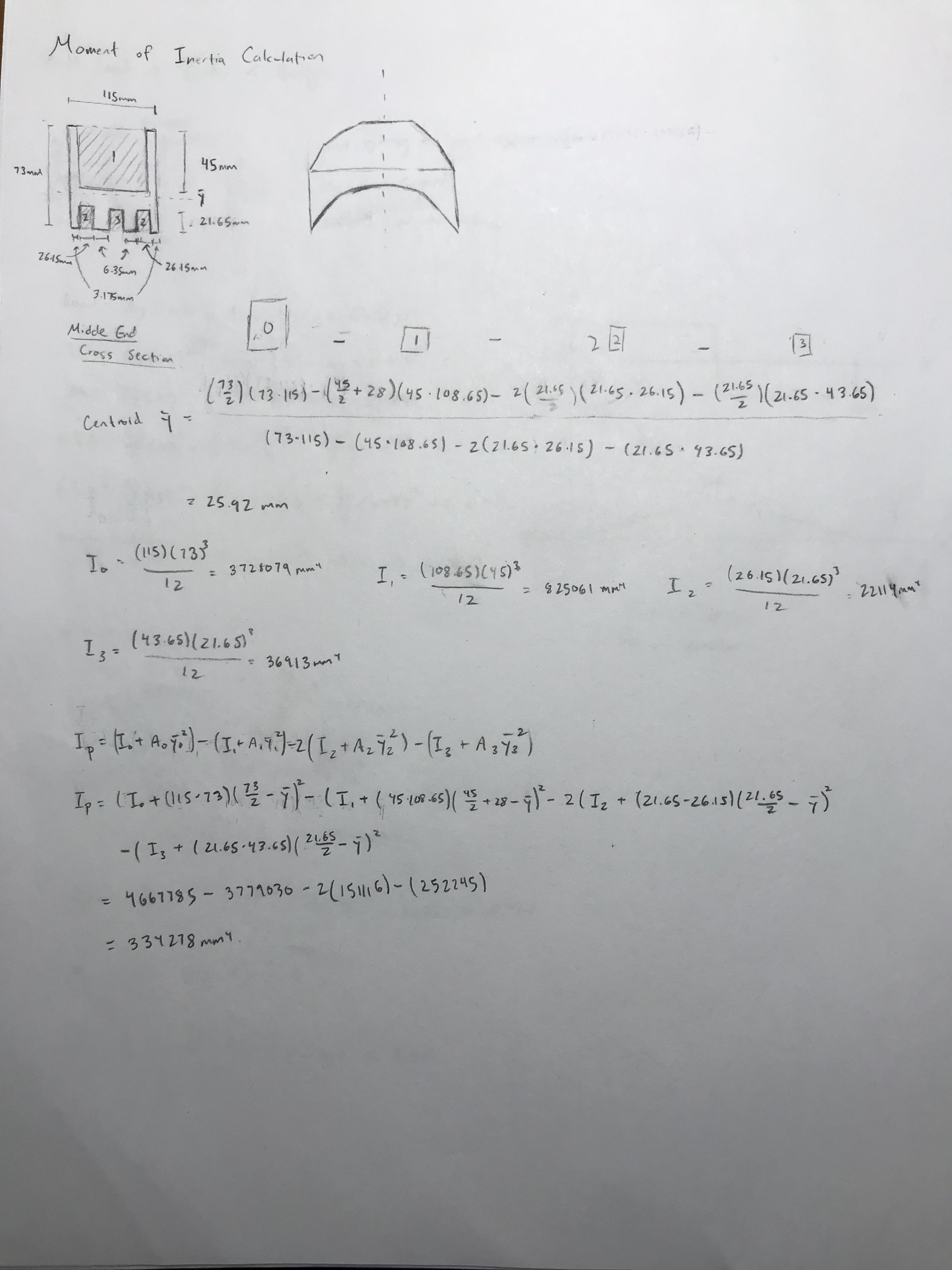
Following our FEA results, we decided to stick with our initial shape of a K-truss bridge and lower arched structure. The FEA informed our design decisions to construct a bridge with an even number of equally spaced top beams with an outermost height of 60 mm, middle width of 90 mm, and an inner width of 200 mm to distribute the load most effectively and result in the lower maximum stress. After finalizing our design, we performed hand calculations on our bridge's maximum load and maximum deflection at a load of 1 kN. We predicted a maximum load of 3.670 kN, a maximum deflection of 0.10 mm, and failure at the beams on top of the support pins of our bridge.
Upon testing, we correctly predicted the location of failure. We also found that our prediction for max load was 95% accurate from the true max load (3.494 kN), but our prediction for max deflection was only 7% accurate from the true deflection (1.46 mm). One potential reason for why our max deflection prediction was so off is due to the SolidWorks mesh possibly overestimating the strength of a glue joint between the top beams and the outer frame of our bridge.
Key Takeaways
This project was an incredible application of mechanical design and solid mechanics theories. With so many design constraints and a priority of optimization, we were challenged to continuously iterate and analyze our designs. As such, this project honed my skills with CAD software, specifically with assemblies, mating, FEA, and Simulation Xpress. Also, in order to predict the maximum load and maximum deflection, we had to draw on our theoretical knowledge of beam, truss, and deflection calculations. This taught me to pay close attention to detail, as well as understand how to make logical assumptions in hand calculations.
As another team project, this project particularly highlighted the power of teamwork to me; we were only able to thoroughly design and analyze multiple iterations of our preliminary design within such a short time frame because we could distribute the work among ourselves.
This project was really enjoyable, and this experience (along with the other components of the class itself) is one of the main reasons why I decided to pursue mechanical track within engineering.
Skills & Documentation
Skills: SolidWorks | FEA | Design for Assembly | Laser Cutting
Documentation: Project Description, Written Report, Design Iterations Analysis
A special thanks to my teammates: Caroline Lauer & Dan Phan
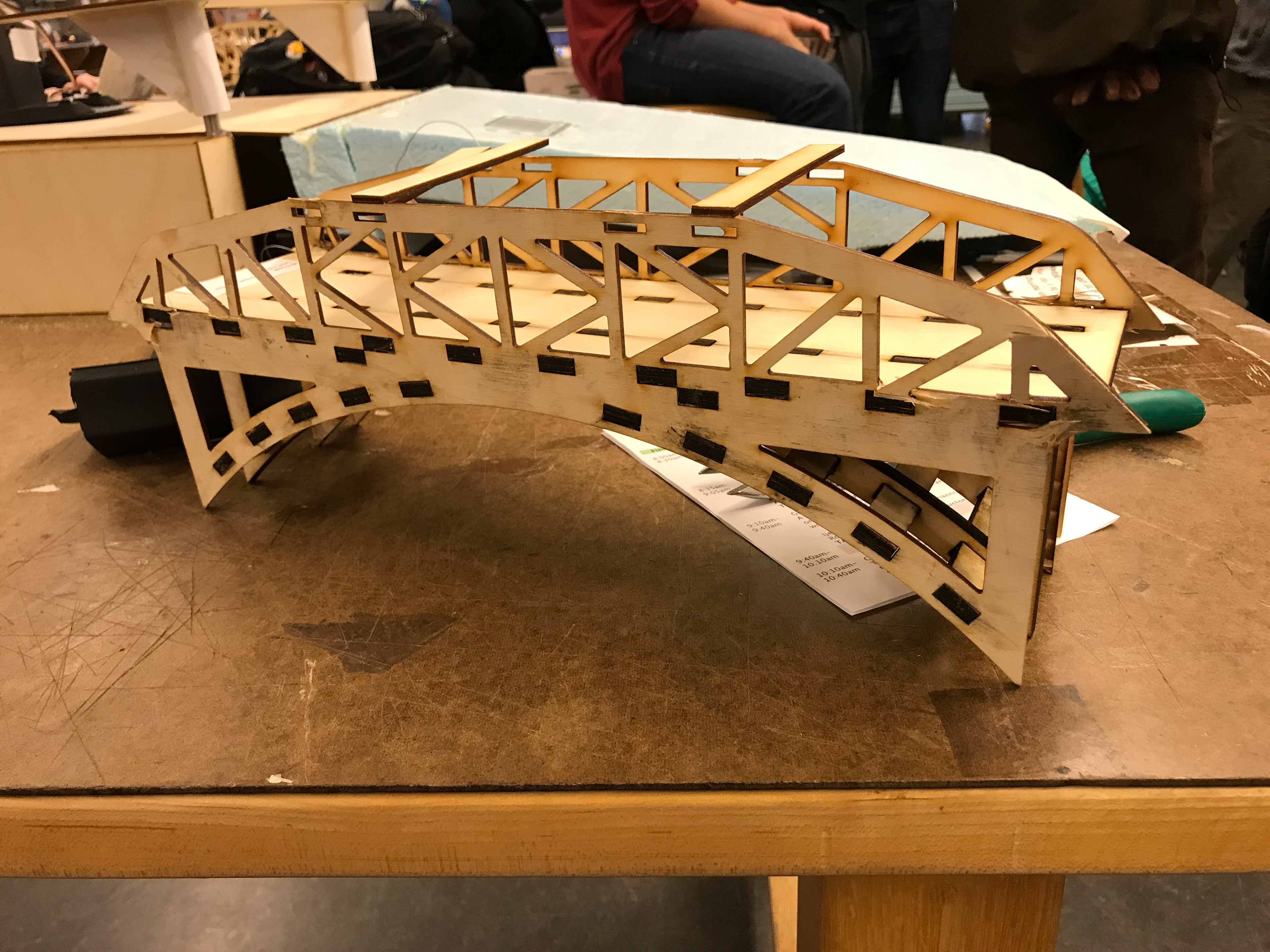
Failure: Front View
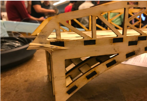
Failure: Close View
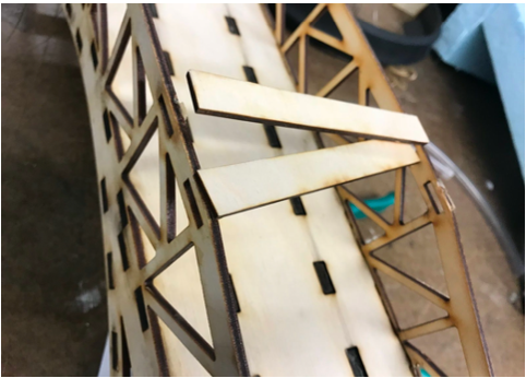
Failure: Top View
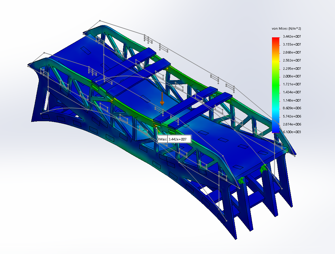
FEA: Max Stress
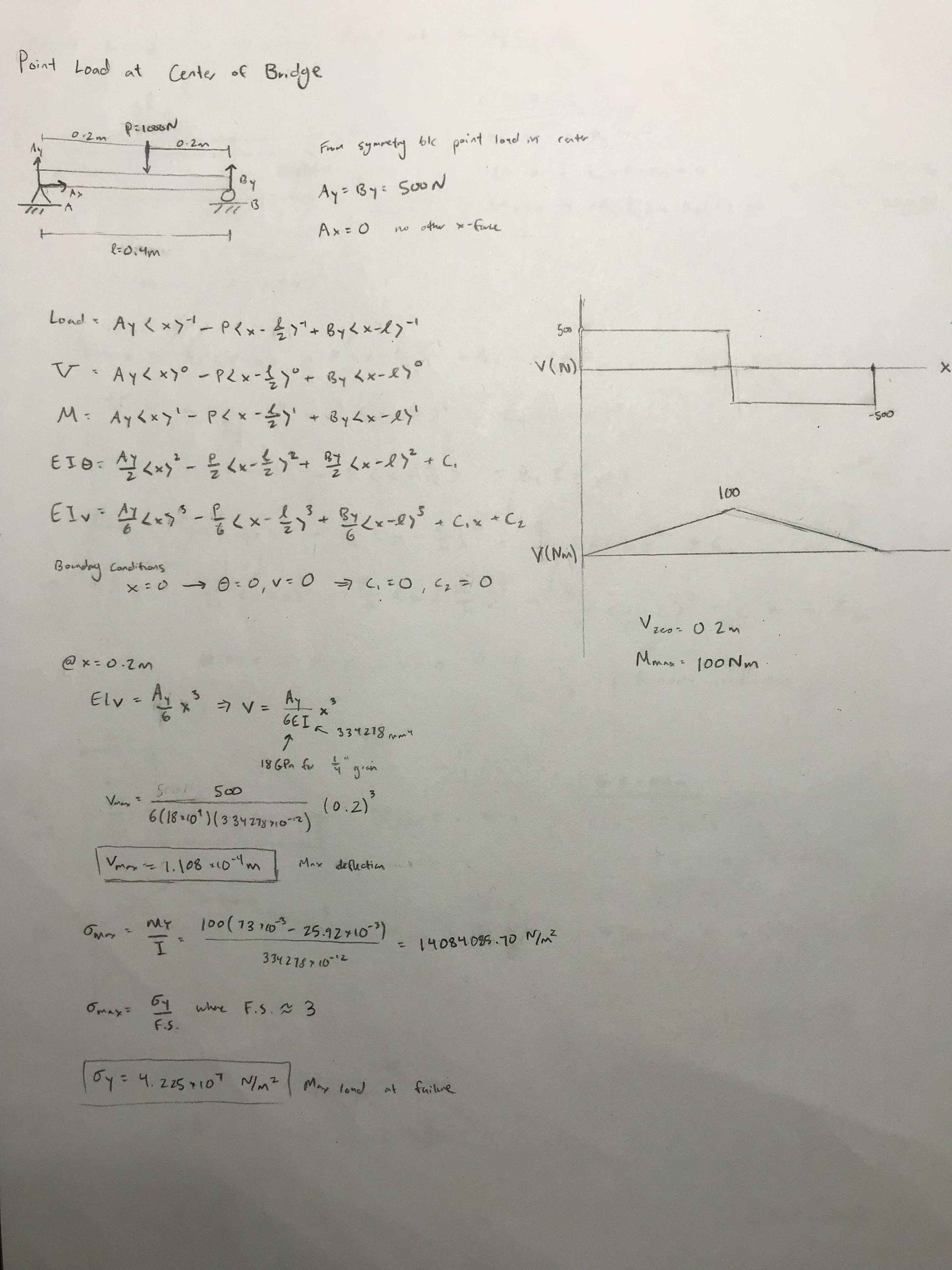
Calculation: Point Load @ Center
